Content
A precision machining shop in Ohio ran a batch of 316L stainless steel parts through a new 5‑axis machining center without any thermal compensation and scrapped 14 out of 100 components. The rejected parts showed dimensional drift of up to 18 microns on critical bore diameters. The cause was not tool geometry or spindle runout; it was the cumulative effect of thermal expansion that had never been actively managed.
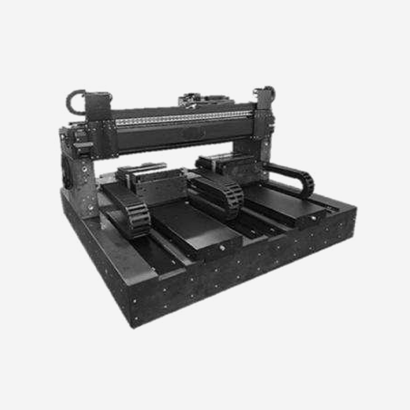
Precision machined part accuracy is the measure of how closely a manufactured component matches its design specifications. In high‑value industries such as aerospace, medical devices, and automotive powertrain, holding tolerances within ±5 microns is not a luxury—it is a contractual requirement. Achieving that level of consistency demands control over six interdependent factors: thermal behavior, machine rigidity, tool condition, material properties, cutting parameters, and operator expertise.
Temperature is the silent enemy of precision. Even a 1°C change in ambient temperature can expand a 300‑mm steel part by nearly 3.5 microns—enough to reject a tight‑tolerance component. Machine tools generate heat through spindle rotation, cutting friction, and hydraulic systems. Without active cooling, this thermal drift accumulates unpredictably. Modern machining centers employ coolant systems with ±0.5°C stability, and many integrate thermal sensors that feed back to the CNC in real time. For critical operations, we recommend climate‑controlled enclosures that maintain 20°C ± 0.2°C. This single investment often reduces scrap rates by over 40% in high‑volume production.
Thermal drift contribution by machine source
Percentages represent average contribution to total thermal error in typical milling operations. Values vary with machine design and operating conditions.
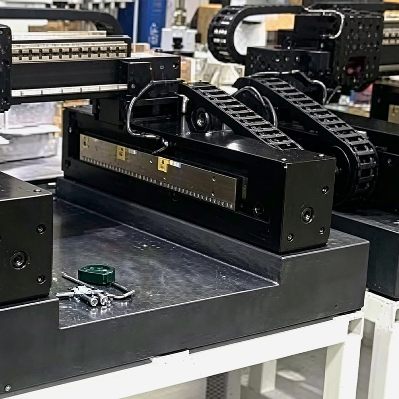
Every cutting operation generates vibration—the question is how well your machine absorbs it. Low rigidity leads to chatter, which leaves visible marks and causes tool deflection. A rigid machine frame, often made of polymer concrete or cast iron, can dampen frequencies up to 200 Hz, while lightweight structures resonate at higher amplitudes. Tests show that increasing static stiffness by 25% improves surface finish by almost one Ra grade. Active damping systems, such as tuned mass dampers or piezoelectric actuators, can further reduce vibration by 60–70%, enabling higher spindle speeds without sacrificing accuracy.
Vibration amplitude vs. cutting speed
Relative amplitude normalized to maximum vibration at low speed. Optimal range corresponds to 60‑80% of maximum spindle speed with active damping engaged.
Tool condition is arguably the most operator‑controllable factor. A worn tool produces higher cutting forces, generates more heat, and leaves a poor surface finish. Replacing inserts after every 200–300 parts, depending on material, is a common practice. Coated tools (TiAlN, AlCrN) extend life by up to 300% and reduce built‑up edge. Moreover, the tool's rake angle and clearance angle must be matched to the workpiece material—for example, a positive rake for aluminum, negative for hardened steel. Our precision machining capabilities include tool condition monitoring systems that detect wear in real time, preventing costly deviations.
Tool life by coating type (hours)
Test conditions: carbide inserts, 316L stainless steel, constant cutting speed and feed rate. Coated tools show significantly extended tool life.
Not all metals are created equal. Free‑cutting steels such as 12L14 machine easily, while superalloys like Inconel 718 are notoriously difficult. Material hardness, ductility, and thermal conductivity all influence cutting forces and tool wear. For example, titanium alloys require low cutting speeds and high feed rates to avoid work hardening. A simple machinability index, based on tool life and surface finish, can guide process planning. A proprietary database covering over 200 materials helps in recommending ideal parameters for each job.
High machinability materials
Low machinability materials
Speed, feed, and depth of cut form the "golden triangle" of machining. Running too fast sacrifices tool life; too slow reduces productivity. Advanced CNC systems use adaptive control to maintain constant chip load, automatically adjusting feed rates to compensate for tool wear or material variations. A well‑optimized set of parameters can improve accuracy by 15–20% while reducing cycle time. Design‑of‑experiments (DoE) is used to find the sweet spot for each job, balancing surface finish, dimensional stability, and throughput.
Even the most advanced machine relies on skilled operators. Understanding tool wear patterns, interpreting surface finish, and making micro‑adjustments can save thousands of parts from scrap. Investment in continuous training and encouraging operators to share insights across shifts yields significant returns. A culture that values precision over speed—and rewards problem‑solving—often yields the highest accuracy gains. Internal metrics show that shops with engaged operators have 30% fewer quality alerts and 25% higher first‑pass yield.
| Factor | Impact on accuracy | Mitigation approach |
| Thermal drift | ± 10–20 µm | Coolant control, climate enclosure |
| Vibration | ± 5–15 µm | Rigid frame, active damping |
| Tool wear | ± 8–25 µm | Coated tools, real‑time monitoring |
| Material variability | ± 3–12 µm | Pre‑selection, batch testing |
| Cutting parameters | ± 4–18 µm | Adaptive control, DoE optimization |
| Operator skill | ± 5–15 µm | Training, standard work procedures |
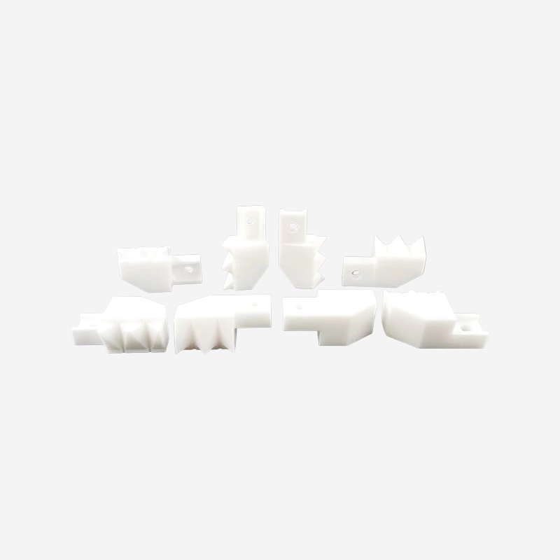
Specializing in ultra-tight tolerances, our machined ceramic plates and custom parts are tailored to...
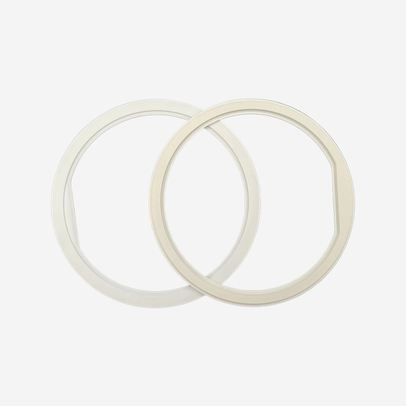
A comprehensive range of high-performance ceramic spares designed to replace traditional metal parts...
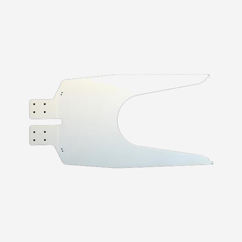
Product Features Performance advantages: High hardness (Vickers hardness over 2000HV, wear-resistant...
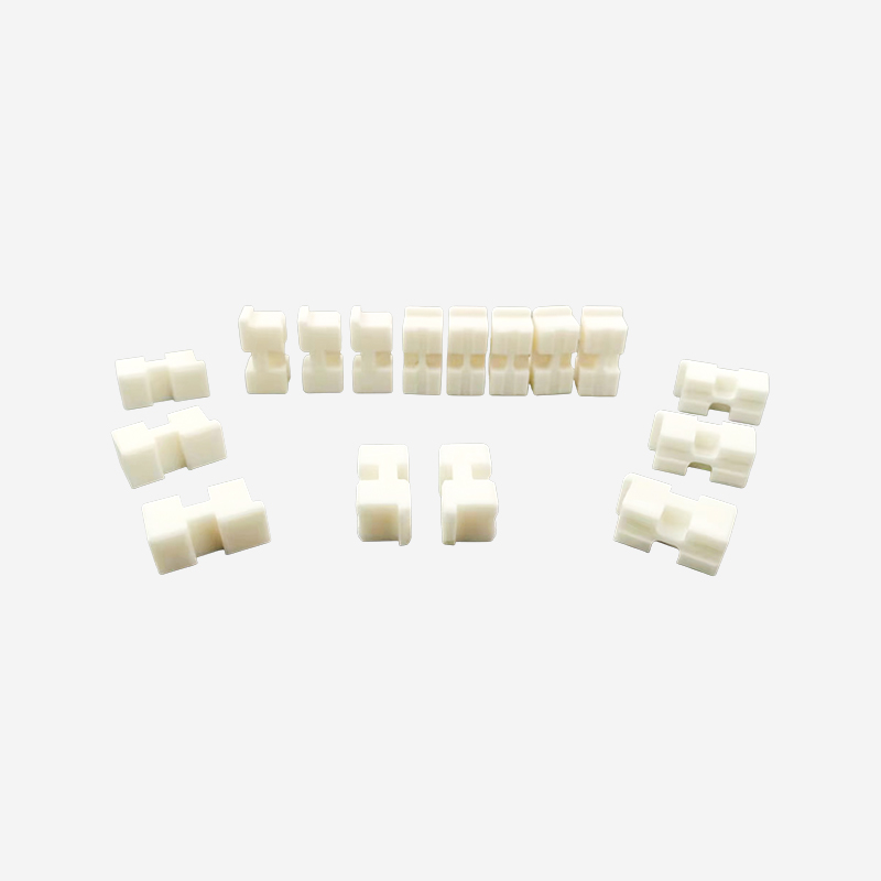
Custom-engineered structural components that combine the high-purity properties of alumina with comp...
Ready to Innovate Together? Contact Our Experts.

Contact Us
Address: 288 Shande Road, Shanyang Town, Jinshan District, Shanghai, China TEL/WhatsApp:Mobile terminal




 English
 日本語
日本語
 عربى
عربى
 中文简体
中文简体