How do you properly design vacuum system piping to minimize conductance losses?
Conductance losses in vacuum piping directly determine the effective pumping speed at the process chamber, affecting cycle times, base pressure achievement, and overall system performance. Proper piping design requires understanding the relationship between pipe geometry, flow regimes, and component selection. SUNFUN Group, with four decades of experience in vacuum component manufacturing, applies precision engineering principles to produce piping systems that deliver optimal conductance while maintaining structural integrity and clean vacuum conditions.
Product Category 1: Straight Piping Sections and Tubing
Definition and Positioning
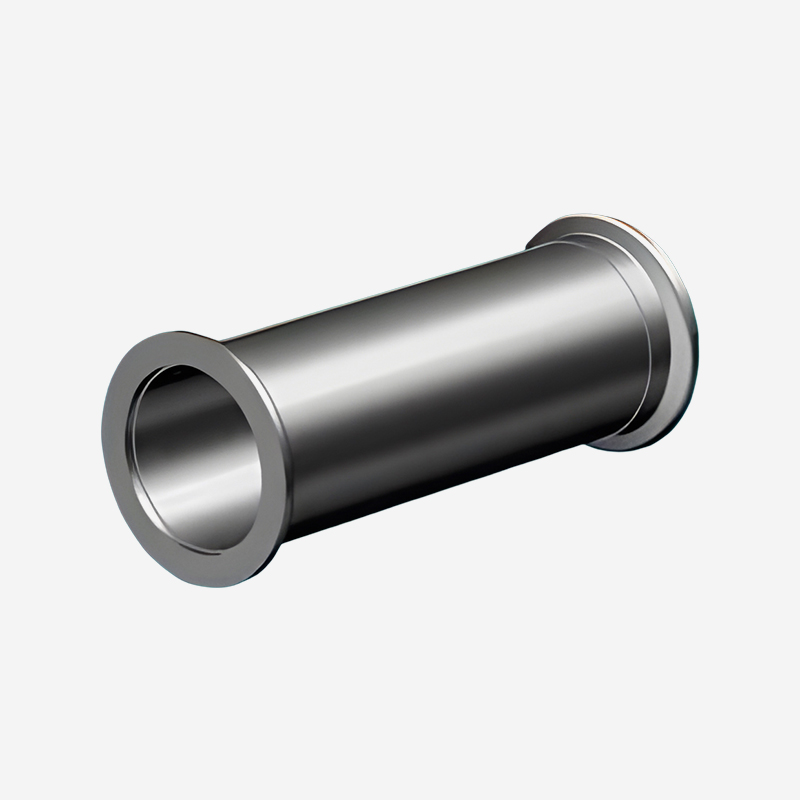
Straight piping sections form the primary pathways for gas flow between the vacuum pump and the process chamber. These tubular components are available in various diameters and wall thicknesses, fabricated from materials selected for outgassing performance and corrosion resistance. SUNFUN Group produces straight piping from stainless steel, aluminum, and specialty alloys, with surface finishes appropriate for the intended vacuum level. The selection of pipe diameter represents the single most important decision in vacuum piping design—conductance increases with the fourth power of the diameter in molecular flow conditions, making diameter the dominant factor in determining system conductance.
Core Functions and Technical Features
The primary function of straight vacuum piping is to transport gas molecules from the chamber to the pump with minimal resistance. In viscous flow conditions at pressures above 10⁻³ mbar, conductance depends on pipe diameter, length, and the viscosity of the gas being pumped. As pressure decreases and the system enters molecular flow—typically below 10⁻³ mbar—conductance becomes independent of pressure and depends only on the pipe geometry and the molecular velocity of the gas. In molecular flow, the conductance of a straight pipe is determined by its diameter and length, with diameter having the fourth-power relationship: doubling the diameter increases conductance by a factor of sixteen. This relationship makes diameter selection the most effective design parameter for minimizing conductance losses in vacuum system piping.
The interior surface condition of vacuum piping is equally important in controlling conductance. Smooth interior surfaces reduce the wall friction that impedes gas flow in both viscous and molecular flow regimes. SUNFUN Group's straight piping sections are manufactured with surface finishes that minimize gas adsorption and particle generation. Electropolished stainless steel surfaces with roughness values below 0.8 µm Ra provide the low outgassing and smooth gas flow characteristics required for semiconductor and research applications. These manufacturing practices result in vacuum piping components that maintain consistent conductance while meeting cleanliness specifications for the most demanding applications.
Typical Application Scenarios
Straight piping sections are used across all vacuum applications, from rough pumping lines in industrial processes to UHV beamlines in research facilities. In semiconductor manufacturing, stainless steel tubing with electropolished interiors connects process chambers to turbo-molecular pumps and cryogenic pumping systems. In industrial coating systems, aluminum tubing provides the high conductance required for rapid pump-down while handling the moderate vacuum levels used in these applications. Research installations—including surface science instruments and particle accelerators—use straight stainless steel piping with CF flanges for UHV compatibility.
Differentiation from Other Components
Straight piping sections are distinguished from other vacuum components by their geometric simplicity and their role as the primary conductance path. Unlike elbows, tees, or cross fittings—which introduce additional flow resistance through direction changes—straight sections offer the highest possible conductance for a given diameter. The design objective for straight piping is to maximize conductance by selecting the largest practical diameter and shortest possible length while maintaining compatibility with other system components. This principle—known as the "short and wide" rule—represents the foundational guideline for vacuum system piping design.
SUNFUN Group's Piping Manufacturing Capabilities
SUNFUN Group's straight piping production benefits from precision machining and surface treatment capabilities developed over four decades. Our electropolishing and passivation processes achieve the surface finishes required for clean vacuum applications. Through our accredited technology enterprise status and national-level R&D achievements—including projects commissioned by the NDRC, MOST, and MIIT—we maintain quality systems that ensure consistent piping fabrication. Our in-house institute and talent academy provide the technical expertise for developing improved surface treatments and manufacturing techniques for vacuum pipe components.
Design Specifications for Straight Piping
- Diameter selection: Based on pump inlet size and required conductance
- Length minimization: Shorter runs reduce conductance losses
- Surface finish: Electropolished to Ra ≤ 0.8 µm for clean applications
- Materials: 304/316L stainless steel, aluminum, specialty alloys
- Flange compatibility: KF, ISO, CF standards as specified
- Bakeout capability: Compatible with system bakeout procedures
Product Category 2: Vacuum Elbows and Directional Components
Definition and Positioning
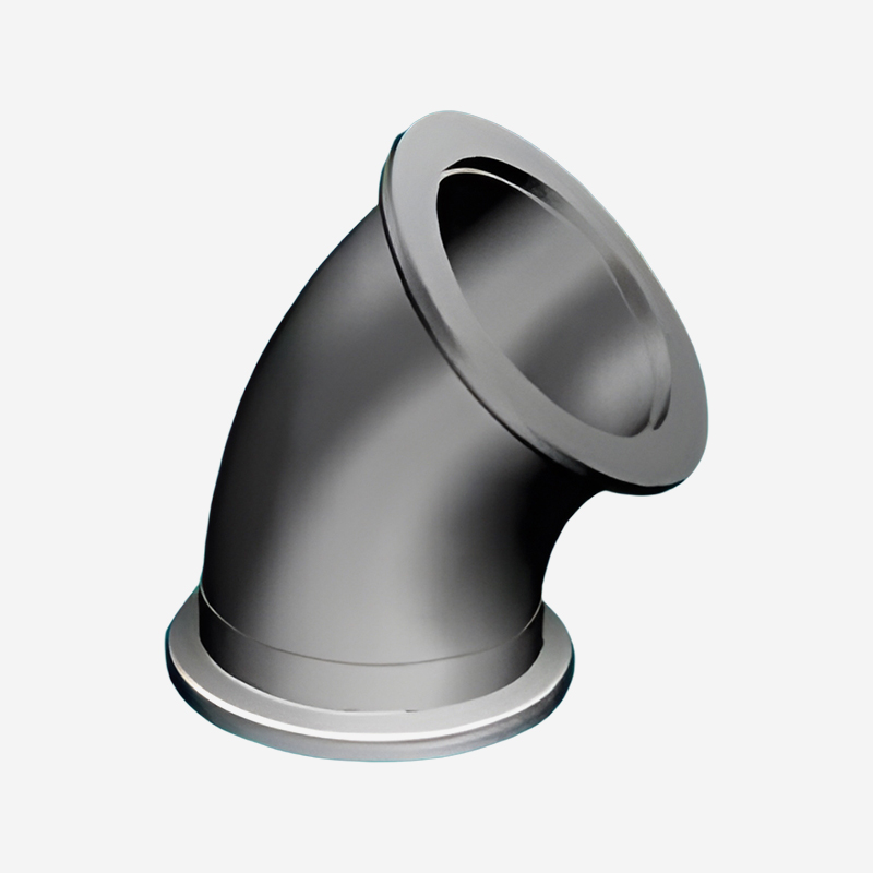
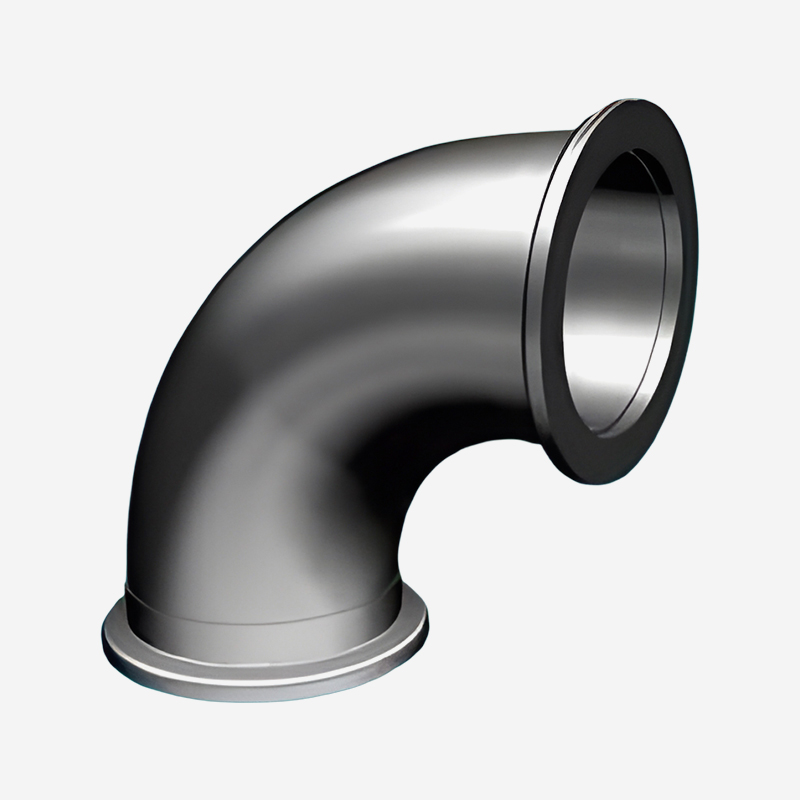
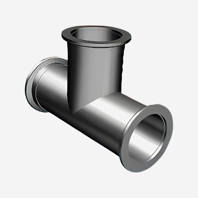
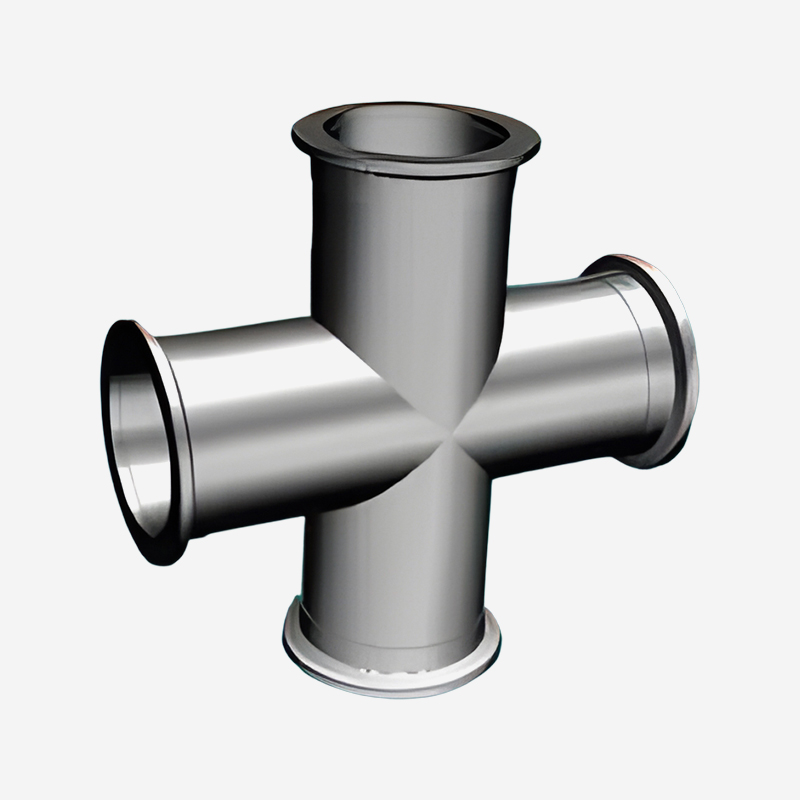
Vacuum elbows and directional components—including 45° and 90° bends, tees, crosses, and offset sections—enable the routing of vacuum piping around obstacles and between equipment in different positions. These components introduce additional conductance losses due to flow direction changes and the increased surface area they present to gas molecules. The design of elbows and directional components must balance the mechanical requirements of system layout with the need to minimize added resistance, particularly in systems where conductance is critical.
Core Functions and Technical Features
The primary function of elbows and directional components is to change the flow path direction while maintaining a defined cross-section and vacuum integrity. The conductance loss introduced by an elbow depends on its radius of curvature and the angle of direction change. Gentle bends with large radii—typically five to ten times the pipe diameter—allow smoother flow transitions and reduce the impact on conductance. Sharp 90° bends, by contrast, introduce significant conductance losses. In molecular flow, the conductance of a 90° elbow is approximately 60‑70 % of the conductance of a straight pipe of equivalent diameter and length. This reduction is due to the increased surface area presented to gas molecules and the additional collisions resulting from flow direction changes.
The design of elbows and directional components also must consider cleanability and internal surface quality. These components are typically fabricated from bent tubing or from welded sections with precision-machined internal surfaces. In UHV applications, elbows are usually manufactured from bent stainless steel tubing with electropolished internal surfaces, with smooth transitions at welded joints to minimize areas where contaminants can accumulate. These design considerations address both the conductivity and cleanliness requirements of vacuum piping in sensitive applications.
Typical Application Scenarios
Elbows and directional components are required wherever vacuum system layout involves direction changes. In semiconductor fabrication facilities, vacuum piping must be routed to connect process tools to centralized pump systems, requiring multiple bends and directional changes to navigate cleanroom layouts. Research facilities with complex instrument arrangements require custom elbows and directional components to connect chambers to pumping systems across limited floor spaces. Industrial coating systems—with their larger pipe sizes—use fabricated elbows and tees to connect pumps, chambers, and trap systems.
Differentiation from Straight Piping
Elbows and directional components differ from straight piping sections in their conductance characteristics and the design principles applied to their specification. While straight sections should be specified with the largest practical diameter and shortest length, elbows should be specified with the largest possible radius of curvature and the smallest necessary angle of direction change. The use of multiple 45° bends in place of a single 90° bend can sometimes provide lower total conductance loss than a single sharp bend. These principles guide the engineering of vacuum system piping to maintain system conductance while meeting layout requirements.
SUNFUN Group's Directional Component Capabilities
SUNFUN Group manufactures elbows and directional components with attention to conductance preservation and internal surface quality. Our tube bending processes produce consistent, wrinkle‑free bends for applications requiring large radii. Our welding and assembly techniques maintain internal surface quality at joint locations. Our in-house institute provides engineering support for custom directional component designs that address specific layout requirements. Our accredited technology enterprise status ensures quality systems that support consistent fabrication of vacuum pipe components.
Elbow Design Specifications
- Bend radius: Minimum 5× diameter for reduced conductance losses
- Angle options: 45°, 90°, and custom angles
- Surface finish: Electropolished or mechanically polished as specified
- Fabrication: Bent tubing or welded sections with smooth transitions
- Flange compatibility: KF, ISO, or CF standards
- Inspection: Visual and dimensional checks for surface quality and accuracy
Product Category 3: Flanges, Gaskets, and Connection Hardware
Definition and Positioning
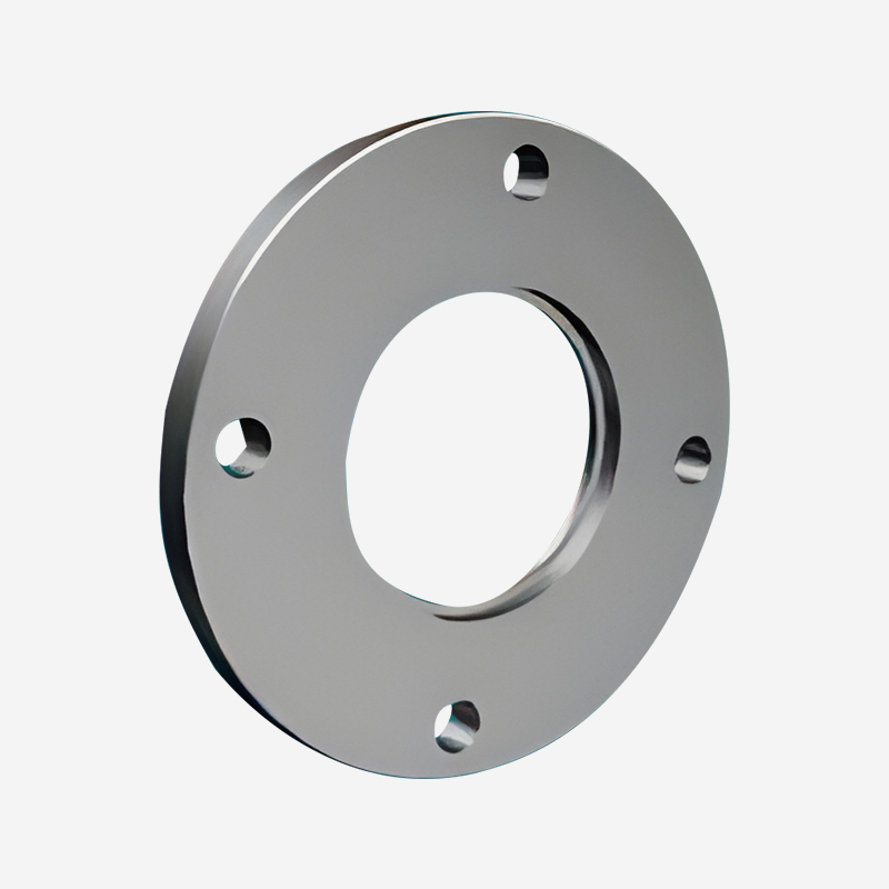
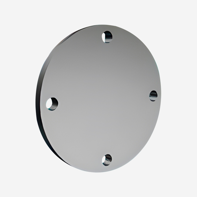
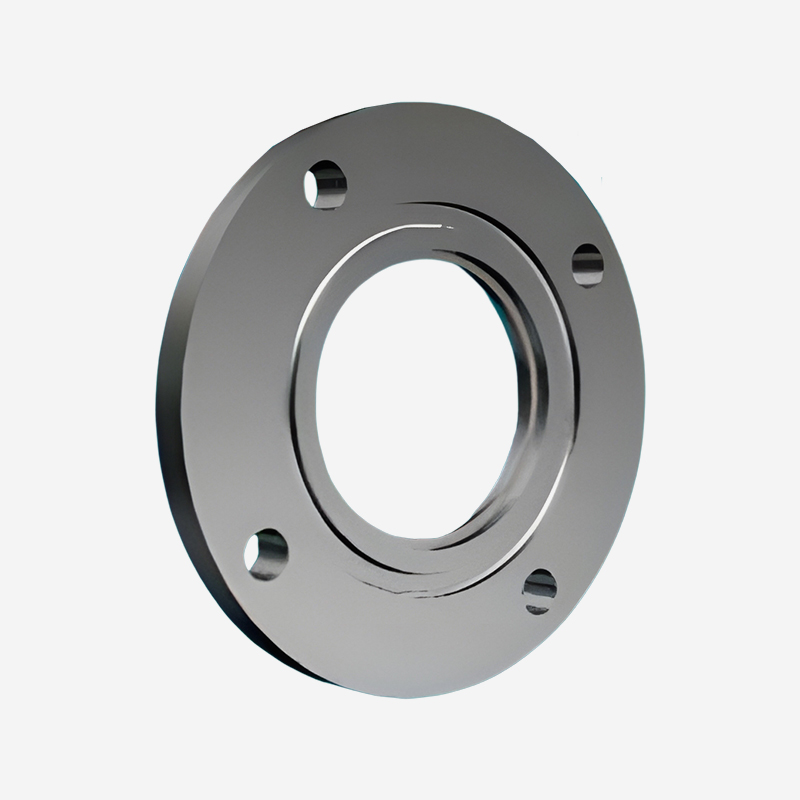
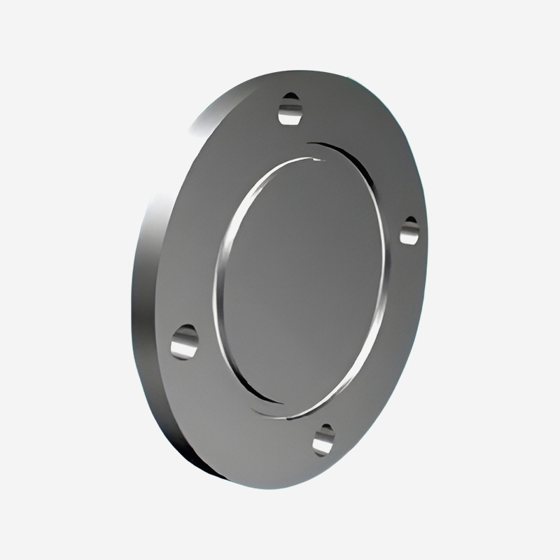
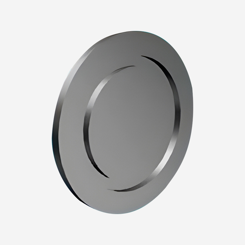
Flanges, gaskets, and connection hardware are the enabling components that make vacuum piping systems practical and maintainable. These items provide the mechanical connection between pipe sections and other vacuum components, establishing leak‑tight seals that maintain system vacuum integrity. The selection and installation of flanges and gaskets directly affect the performance of vacuum system piping, as leakage or poor connections create virtual leaks that degrade ultimate pressure and increase contamination risk.
Core Functions and Technical Features
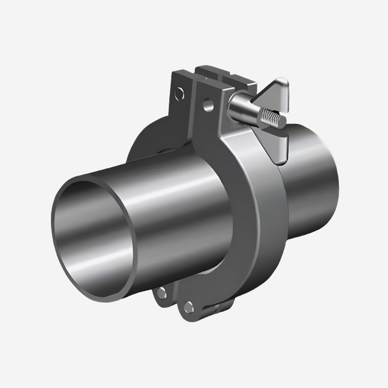
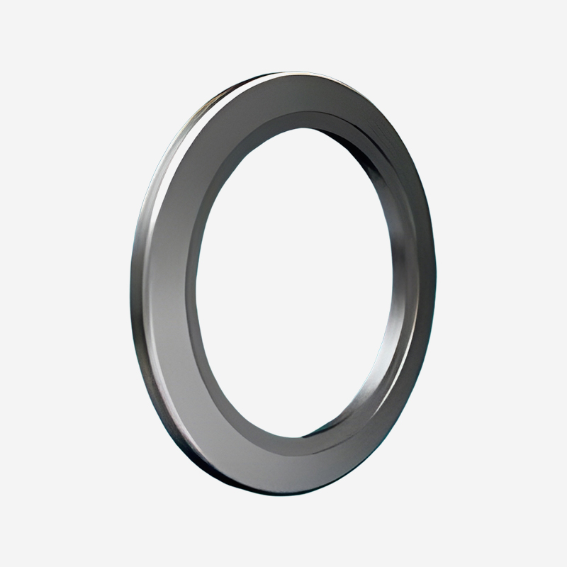
The primary function of flanges and gaskets is to create a reliable, re‑usable seal between vacuum components that maintains integrity across thermal cycling and pressure changes. In standard industrial vacuum applications, elastomer O‑rings—typically made from NBR or FKM—provide economical sealing for pressure ranges down to 10⁻³ mbar. These seals are effective and re‑usable, though they require replacement periodically as the elastomer material ages. For high and ultra‑high vacuum applications, metal gaskets (typically copper or aluminum) used with ConFlat (CF) flanges provide the leak‑tight performance required for UHV conditions. Metal gaskets are single‑use components that are replaced after each opening of the vacuum connection.
The design of flanges and gaskets has evolved to address specific requirements for different vacuum regimes. KF (Klein Flange) systems with quick‑release clamps serve as standard connections for rough and medium vacuum applications. ISO flanges with bolted clamps provide larger diameter connections for high vacuum applications requiring good conductance. ConFlat flanges with the knife‑edge sealing surface and copper gaskets are standard for UHV applications. Each system offers specific advantages in terms of installation convenience, cost, maintenance, and the maximum achievable pressure. SUNFUN Group's vacuum pipe components are available in all major flange standards.
Typical Application Scenarios
Flanges and gaskets are used in every vacuum piping installation, regardless of application or pressure range. Semiconductor fabs use CF flanges for UHV connections on process tools and ISO flanges for backing lines and roughing systems. Research laboratories typically use CF flanges for their UHV systems and KF flanges for less demanding connections. Industrial vacuum systems for packaging and drying use KF or ISO flanges for their ease of installation and maintenance.
Differentiation from Piping Sections
Flanges and gaskets differ from pipe sections and directional components in their role in the vacuum system. While pipe sections establish the pathway for gas flow, flanges and gaskets provide the means to assemble and maintain that pathway. The specification of flanges and gaskets requires consideration of re‑use cycles, bakeout temperature compatibility, and contamination control—dimensions that apply to connection hardware rather than to the flow path itself. The selection of appropriate flange systems is the foundation for effective vacuum system piping design.
SUNFUN Group's Connection Hardware Capabilities
SUNFUN Group manufactures flanges, gaskets, and connection hardware across all major standards. Our precision machining capabilities produce flange faces with the surface finishes required for reliable sealing. Our in-house institute supports quality control processes including leak testing of assembled components. Our accredited technology enterprise status ensures compliance with international flange standards and quality specifications. Through our open innovation ecosystem, partnering with governments, enterprises, universities, and institutions, we maintain awareness of evolving flange standards and sealing technologies that may benefit our customers.
Key Specifications Comparison
| Parameter |
KF (Quick‑Clamp) |
ISO (Bolted) |
CF (ConFlat) |
| Pressure range |
Atmosphere – 10⁻⁶ mbar |
Atmosphere – 10⁻⁸ mbar |
Atmosphere – 10⁻¹² mbar |
| Seal type |
Elastomer O‑ring |
Elastomer O‑ring |
Metal gasket (copper/aluminum) |
| Bakeout temperature |
≤ 120 °C |
≤ 120 °C |
≤ 450 °C |
| Seal re‑usability |
Yes (multiple cycles) |
Yes (multiple cycles) |
Single use (replace after opening) |
| Diameter range |
DN 10 – DN 50 |
DN 63 – DN 500 |
DN 16 – DN 400 |
Proper vacuum system piping design requires coordinated selection of straight sections, elbows, and connection hardware, with each component chosen to maintain conductance while satisfying layout and operational requirements. SUNFUN Group provides comprehensive vacuum piping solutions across all component categories, applying precision manufacturing and quality assurance to support our customers' vacuum system requirements. Through our accredited technology enterprise status and national-level R&D achievements, we maintain the technical expertise required for effective vacuum piping design and fabrication.
Frequently Asked Questions
Q1: What is the most important factor in minimizing conductance losses in vacuum piping?
Pipe diameter is the most critical factor—conductance increases with the fourth power of the diameter in molecular flow. Selecting the largest practical diameter for each section of vacuum piping reduces conductance losses more effectively than other design choices.
Q2: How does pipe length affect vacuum system conductance?
Conductance decreases as pipe length increases—longer pipes present more resistance to gas flow. The relationship is inversely proportional to length in molecular flow. Designing the shortest practical run for vacuum system piping minimizes these losses.
Q3: What surface finish is appropriate for semiconductor vacuum piping?
Electropolished stainless steel with surface roughness below 0.8 µm Ra is typically specified for semiconductor vacuum pipe components, as this finish provides low outgassing, minimal particle generation, and improved conductance characteristics.
Q4: How does SUNFUN Group ensure quality in vacuum piping manufacturing?
SUNFUN Group applies material certification, dimensional inspection, surface finish verification, and leak testing to all vacuum piping components. Our accredited technology enterprise status supports comprehensive quality systems, and our in-house institute and talent academy provide technical oversight for piping production. Our open innovation ecosystem ensures continuous improvement in manufacturing methods.


 English
 日本語
日本語
 عربى
عربى
 中文简体
中文简体