
 English
 日本語
日本語
 عربى
عربى
 中文简体
中文简体


High Vacuum and Ultra-High Vacuum General Semiconductor Vacuum Chambers
Meeting HV and UHV standards, these chambers are rigorously helium leak-tested to ensure ultra-low l...

Content
A researcher tightens a CF flange, fires the backing pump, and watches the ion gauge climb past 10⁻⁸ mbar. Then it stalls. The system holds at low vacuum, but the ultra high vacuum range remains out of reach. This scenario plays out in labs and production lines more often than most engineers care to admit — and in nearly every case, the culprit is not the pump or the gauge, but the components themselves.
Ultra high vacuum (UHV) systems demand a different mindset from ordinary high vacuum setups. In the pressure range below 10⁻⁷ mbar, every material, every weld, every seal, and every surface finish affects the achievable base pressure. Choosing the right ultra high vacuum components therefore is not a matter of preference — it is the difference between a system that reaches 10⁻¹⁰ mbar and one that never leaves the 10⁻⁶ range.
This guide explains how UHV components work, where failures occur, and what to check before you commit to a supplier.
UHV begins where ordinary vacuum physics changes character. Below roughly 10⁻⁷ mbar, gas flow becomes molecular — molecules collide with walls far more often than with each other. Outgassing from surfaces overtakes the original air load as the dominant gas source. And leak rates that are irrelevant at 10⁻⁵ mbar become catastrophic at 10⁻¹⁰ mbar.
For this reason, a genuinely UHV-rated component must satisfy four conditions simultaneously:
These four criteria explain why a standard industrial flange or a commercial ball valve cannot simply be "adapted" for UHV service. The metallurgy, the sealing geometry, and the internal surface state all differ from conventional components.
Material choice determines the theoretical performance ceiling of a UHV system; surface finish determines how close you actually get to that ceiling.
Type 316L stainless steel is the workhorse of UHV construction. Its low carbon content reduces chromium carbide precipitation during welding, and its austenitic structure does not undergo magnetic phase transitions — a critical property when components sit near electron optics or beam paths. Titanium appears where weight or thermal expansion matters. Aluminum is acceptable for some UHV chambers, particularly large ones, provided the surface treatment is appropriate.
Outgassing rate scales with effective surface area. A rough surface with Ra 3.2 µm traps water vapor and hydrocarbons far more aggressively than an electrophished surface at Ra 0.4 µm. For the highest vacuum levels, internal surfaces are typically:
This is why two chambers of identical geometry can have completely different base pressures. The metal is the same; the surface work is not.
Every joint in a UHV system is a potential leak path. The selection of flanges and gaskets therefore determines both the achievable vacuum and the maintenance burden of the system.
For pressures from 10⁻⁷ down to 10⁻¹² mbar, the CF (ConFlat) system dominates. A CF joint uses a knife-edge on each flange face that bites into a soft metal gasket — typically oxygen-free copper or silver-plated OFC — forming a hermetic seal. Because no elastomer is involved, CF joints are bakeable to 450 °C and hold pressure indefinitely once torqued correctly.
What separates a well-made CF flange from a poor one is not the flange blank itself but the knife-edge geometry. Edge sharpness, height uniformity, and surface hardness determine whether the gasket deforms consistently around the full circumference. Inconsistent machining here produces leaks that appear only after thermal cycling.
For applications demanding full UHV compatibility, the practical choice is a certified CF flange pair — non-rotatable for structural connections, rotatable where alignment is difficult.
KF (quick-flange) and ISO flanges use elastomer O-rings — typically Viton or other low-outgassing compounds — compressed between centering rings. These systems are convenient, inexpensive, and entirely appropriate for high vacuum (10⁻³ to 10⁻⁷ mbar). But because elastomers outgas, absorb water, and degrade under baking, KF and ISO joints cannot deliver the base pressures or the bakeout temperatures that true UHV service requires.
That said, hybrid configurations are common in UHV systems: KF joints used on the roughing side, CF joints on the high-vacuum side. Understanding the boundary between them is part of competent system architecture.
In KF and ISO systems, the centering ring does double duty. It centers the flanges, but it also carries one or two O-rings. A ring with the wrong O-ring durometer, the wrong groove depth, or the wrong internal diameter will leak under bake or vibrate loose in pumped systems. These are small parts with oversized consequences.
The vacuum chamber is the stage on which every other component performs. Its design decides how efficiently pumps work, how evenly the system bakes out, and how easily the interior can be cleaned.
Full-penetration welds are non-negotiable in UHV. Spot welds and partial welds create dead volumes that outgas slowly over days or weeks. Every weld seam must be continuous, free of porosity, and ideally ground smooth on the vacuum side to reduce surface area.
The practical rule: if you cannot inspect a weld from the vacuum side, you cannot trust it in UHV.
Passivation restores the protective oxide layer. Electropolishing goes further, removing a controlled layer of material and smoothing microscopic peaks. For UHV chambers used in semiconductor or particle applications, electrophishing to Ra ≤ 0.4 µm with verified cleanliness is standard practice.
Chambers intended for third-generation semiconductor processing, such as SiC equipment, face even tighter material and cleanliness constraints. The chamber itself becomes a process variable.
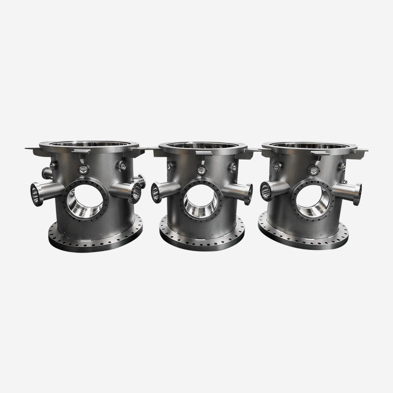 Helium-Leak-Tested HV/UHV Semiconductor Vacuum ChambersThese chambers are designed for demanding semiconductor processes like SiC fabrication, with helium leak testing ensuring ultra-low leak rates. Their rigidity and precision machining suit high-vacuum environments where chamber geometry directly impacts system performance.View Product →
In free-molecular flow, conductance is purely geometric. A long, narrow port connecting a chamber to a pump can reduce effective pumping speed by 10× or more. Designers should place pump ports to minimize path length, avoid right-angle elbows wherever possible, and size all ports assuming the pump is only as effective as the path allows.
Every moving part inside or on a UHV system challenges the sealing philosophy. Valves must isolate sections without introducing outgassing sources; feedthroughs must transmit motion into vacuum without leaking.
Three valve families cover most UHV requirements:
| Valve Type | Seal Mechanism | Typical Range | Bakeability |
|---|---|---|---|
| All-metal angle valve | Copper gasket compressed by wedge | HV to UHV | Up to 300 °C |
| Metal-sealed gate valve | Metal gasket, sliding gate mechanism | HV to UHV | Up to 200 °C |
| Pneumatic bellows valve | Viton O-ring or metal seal, bellows actuator | HV, some UHV models | Depends on seal |
For systems that must isolate a load lock or a process chamber repeatedly, a reliable all-metal gate valve is often the only realistic option. Elastomer-sealed valves will eventually work loose, absorb water vapor, and drag your base pressure upward.
Electrical feedthroughs in UHV typically consist of a conductor brazed into an insulating ceramic, which in turn is welded into a CF flange. Ferrofluid feedthroughs offer rotary motion with exceptionally low leakage but require care around temperature and magnetic fields. Linear and rotary mechanical feedthroughs using differentially pumped O-rings are available, but for UHV service, welded bellows designs are preferred because of zero dynamic leakage paths.
No single pump covers the entire pressure range from atmosphere to 10⁻¹⁰ mbar. A practical UHV pumping stack relies on staged equipment, each stage bridging the pressure gap to the next.
Oil diffusion pumps remain relevant in UHV systems that pump large volumes or handle heavy gas loads. Their lack of moving parts and high throughput at low pressures make them useful in industrial and research settings — provided a cold trap and careful backstream management are in place.
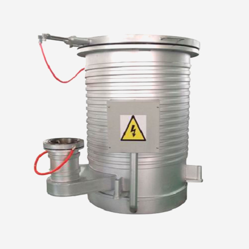 DPM-16 Oil Diffusion Pump with High UHV ThroughputThis pump handles large gas loads in UHV systems without moving parts, making it reliable for industrial and research applications. Its forced water cooling and cold-trap compatibility help manage backstreaming, which is critical for maintaining overall system efficiency.View Product →
The pump that takes the system from atmosphere to high vacuum removes 99.99999% of all gas molecules. If that stage is inefficient, contaminated, or throttled by a clogged foreline, the entire system struggles regardless of the quality of the UHV components downstream.
Assembling a UHV system with premium components is not the finish line — verification is. Two processes dominate the commissioning phase.
At room temperature, a stainless steel surface releases water vapor for months. Bakeout at 150–250 °C accelerates desorption, removing the water layer in hours or days rather than months. Systems intended for 10⁻¹⁰ mbar simply will not reach target pressure without an effective bakeout cycle.
This requirement has practical implications for component selection. Every flange, valve, gauge, and viewport must tolerate repeated thermal cycling without degrading. This is the real reason why elastomer seals fail UHV systems: they char, outgas, or lose compliance after a few bake cycles.
Mass spectrometer leak detection using helium is the gold standard for UHV verification. A well-built system should demonstrate a helium leak rate below 10⁻¹⁰ mbar·L/s. Anything above 10⁻⁸ mbar·L/s indicates a real leak that must be found and repaired before the system enters service.
Component quality varies dramatically between manufacturers. Since most UHV components are installed inside welded assemblies or hidden between flanges, poor quality often surfaces only after weeks of commissioning time is lost.
These questions matter because UHV performance is not visible on a datasheet. The same flange model from different factories can differ in knife-edge quality, internal roughness, and cleaning discipline — yielding orders-of-magnitude differences in base pressure.
Suppliers who have long experience in precision machining understand this. The discipline required to hold 0.001 mm tolerances, manage material certification, and control surface state carries directly into UHV component production. This is one reason why the most reliable UHV parts often come from manufacturers with roots in precision engineering rather than generic fittings and plumbing.
Ultra high vacuum systems reward patience and punish shortcuts. The components you select determine every measurable outcome: base pressure, pump-down time, leak rate, bakeout stability, and the cost of ownership over the system's lifetime.
Start with the seals and flanges, where most failures originate. Then look at the chamber geometry and welds, which decide outgassing and conductance. Choose your valves and feedthroughs based on thermal cycles and reliability, not just list price. And verify everything — because in ultra high vacuum, good intentions do not count, but measured leak rates do.
Ultra high vacuum components are manufactured to lower leak rates, use lower-outgassing materials, resist higher bakeout temperatures, and are cleaned more rigorously than standard high vacuum components. In practice this means metal seals, welded construction, verified leak integrity, and controlled surface treatments.
KF flanges rely on elastomer O-rings absorbing water vapor and deteriorating under heat. They are not suitable for UHV service. Use CF flanges with copper gaskets for UHV connections and reserve KF components for roughing lines and other non-UHV sections.
Ask for material certificates, surface treatment records, helium leak test results, and maximum bakeout temperature. A component advertised as "vacuum-rated" should not be assumed UHV-safe without these verifications.
Zinc-plated steel, cast iron, porous aluminum, and most standard elastomers should not be used inside a UHV chamber. Alloys with high zinc, lead, or sulfur content also outgas excessively. Brass is borderline and should be used only in small quantities with verification.
Check three areas in order: first, for genuine leaks using a helium leak detector; second, for contamination or inadequate bakeout; third, for effective pumping speed at the chamber. In practice most UHV failures trace back to a flange or valve, not the pump or the gauge.
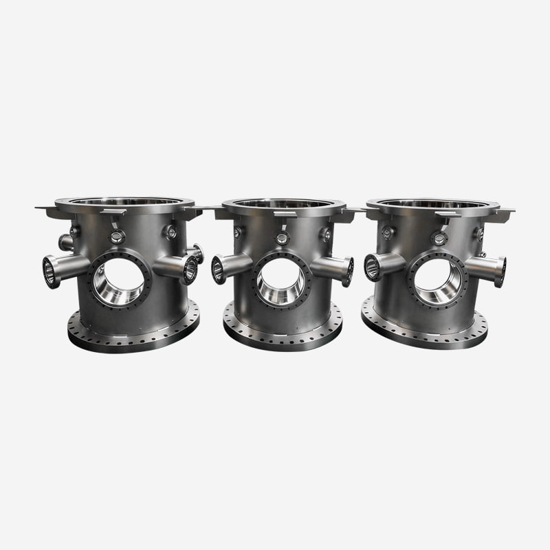
Meeting HV and UHV standards, these chambers are rigorously helium leak-tested to ensure ultra-low l...
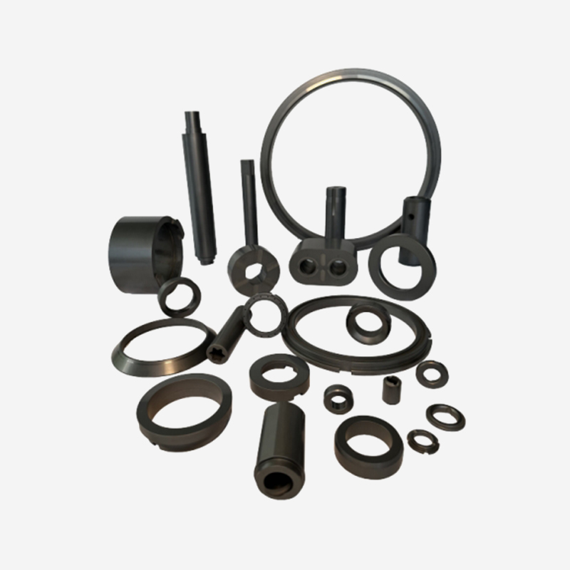
Silicon carbide materials have extremely high hardness and strength, excellent wear resistance and a...
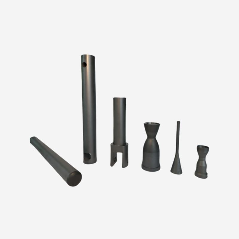
For the most demanding high-temperature applications, sintered silicon carbide outperforms most meta...
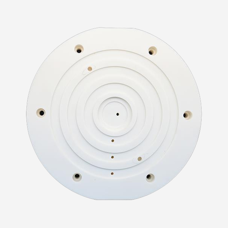
Product Features High cleanliness: Smooth surface, dust-free, suitable for precision workpieces such...
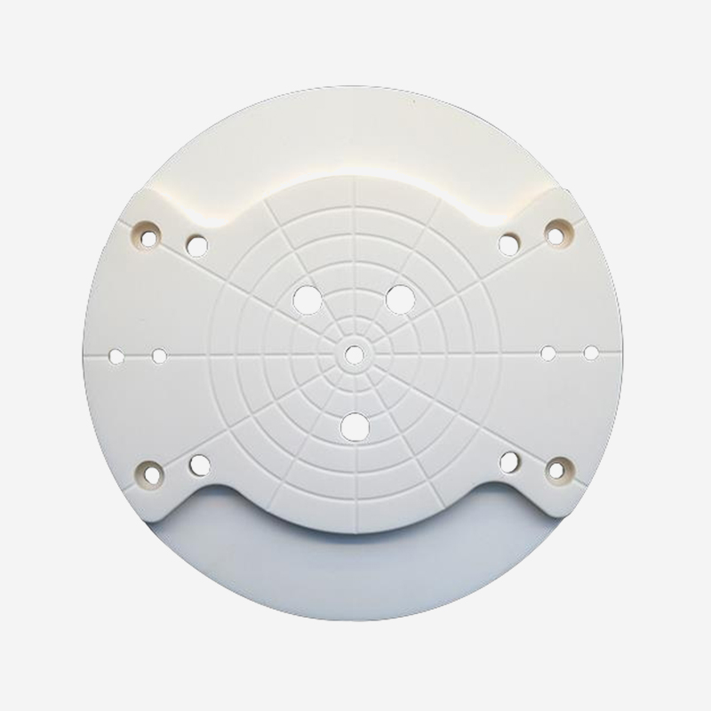
Product Features Clean and precise: Smooth surface (not easy to scratch the workpiece), uniform and ...
Ready to Innovate Together? Contact Our Experts.

Contact Us
Address: 288 Shande Road, Shanyang Town, Jinshan District, Shanghai, China TEL/WhatsApp:Mobile terminal