
 English
 日本語
日本語
 عربى
عربى
 中文简体
中文简体


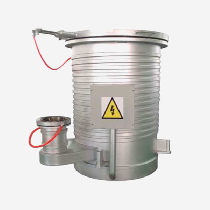
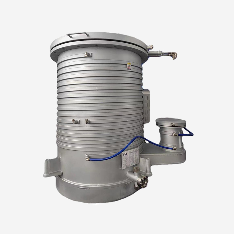
High Vacuum and Ultra-High Vacuum General Semiconductor Vacuum Chambers
Meeting HV and UHV standards, these chambers are rigorously helium leak-tested to ensure ultra-low l...

Content
A coating line stops at the least expected moment. A gate valve, cycled more than a thousand times per day, finally seizes when process residue accumulates on its sliding surfaces. The chamber vents to atmosphere, the entire batch is scrapped, and the maintenance crew spends a full shift replacing the valve. This scenario repeats in production facilities where vacuum components are chosen without considering duty cycles and operating conditions.
The correct approach is to treat a high vacuum gate valve as a process decision, not just a catalog item. Three elements determine whether the valve will deliver years of trouble-free service: the flange standard, the sealing mechanism, and the actuator type. This guide explains how each choice affects real production performance.
A gate valve is a vacuum component that uses a flat, disc-shaped gate to open and close the flow path. The gate moves linearly, either by a linkage mechanism or a steel-ball actuator, and retracts fully from the bore when the valve is open. Two practical advantages follow from this design:
Compared with angle valves and butterfly valves, gate valves are preferred for large-bore isolation where conductance matters. An angle valve forces gas to turn 90 degrees, which can reduce effective pumping speed by roughly 15 to 20 percent in some installations. A butterfly valve seals with a rotating disc, which can trap particles and leave wear marks on the seat. The gate valve avoids both problems, which is why it has become the standard isolation component in vacuum coating systems, semiconductor process tools, and research chamber networks.
Two parameters carry most of the weight in gate valve selection: flange standard and actuator type. Getting these right eliminates the majority of field failures.
The flange standard defines the sealing method, the achievable pressure range, and the contamination level of the vacuum side. This is the first decision because every other component in the system must match the same flange family.
| Flange Standard | Sealing Method | Reachable Pressure | Best For |
|---|---|---|---|
| KF / ISO | FKM O-ring | down to 10-7 mbar | Coating systems, general vacuum, load locks, transfer chambers |
| CF (ConFlat) | Oxygen-free copper gasket | down to 10-10 mbar | UHV research, semiconductor processing, surface analysis, accelerator beam lines |
The actuator determines how automatically the valve can be integrated into a process sequence.
Lowest cost, simple operation, suitable for maintenance and lab use.
Fast response, automated, ideal for production lines with limit switch feedback.
Precise position control, no compressed air required, higher cost.
Manual actuators are the simplest and most economical option. They suit laboratory setups, low-frequency maintenance valves, and systems where compressed air is not available. However, manual operation requires staff to be physically present, which limits automation.
Pneumatic actuators are the industrial standard for production lines. They respond in milliseconds, work reliably over hundreds of thousands of cycles, and can be controlled by simple solenoid valves. A pneumatic gate valve with a limit switch provides open/close status signals to the PLC, enabling automated sequencing.
Electric actuators offer precise position control and are used where the valve must modulate flow or where no compressed air is available. They cost more than pneumatic versions but are indispensable in certain process control architectures.
For high vacuum applications in the 10-5 to 10-7 mbar range, ISO and KF flanges with FKM O-ring seals dominate. These valves handle the routine isolation tasks in coating machines, load locks, and semiconductor cluster tools.
For large bore sizes above 100 mm, a linkage-type gate mechanism is more stable than the traditional steel-ball design. The linkage geometry distributes the closing force evenly across the gate, which reduces local stress and improves vacuum sealing repeatability. This mechanical stability becomes significant when the valve must close against a pressure differential after a roughing pump has evacuated the chamber.
A pneumatic actuator paired with a limit switch is the standard configuration. The switch gives the control system a positive confirmation that the valve has reached its commanded position, which is a prerequisite for automated recipe execution. For example, a sputtering system cannot begin deposition until the gate valve reports fully open, because the chamber could otherwise pressurize above the process setpoint.
When selecting a large-bore gate valve for a coating system, a high vacuum gate valve with ISO flange for large bore lines offers the conductance and cycle life that production systems require.
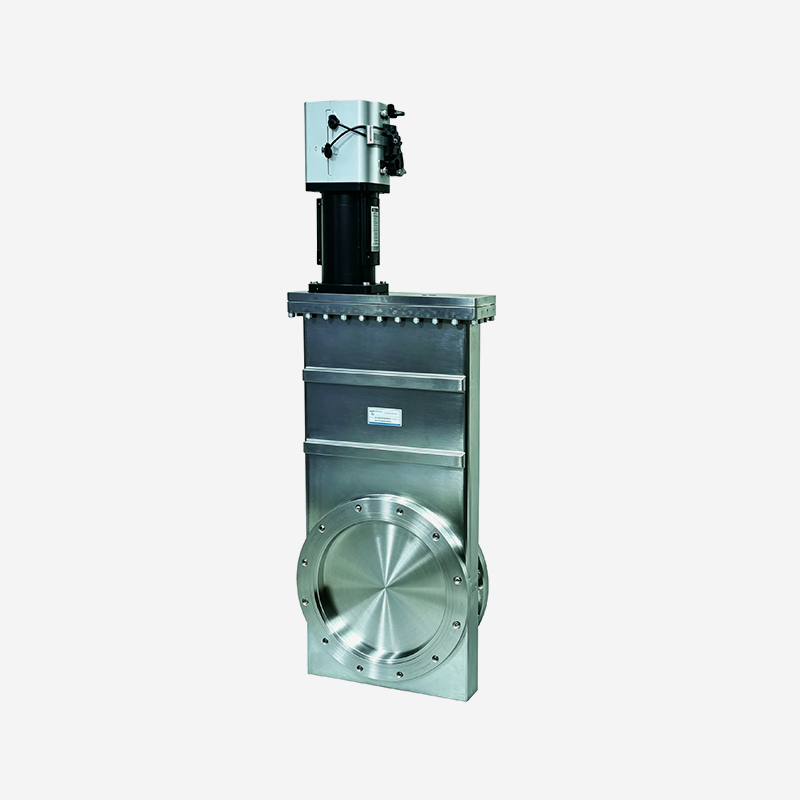 Pneumatic High Vacuum Gate Valve with ISO Flange for Large Bore LinesThis linkage-type pneumatic valve features an ISO flange and bellows, making it suitable for large-bore vacuum lines in coating systems where conductance and cycle life are critical.View Product →
When the system pressure must stay below 1x10⁻⁹ mbar, the valve must use a CF flange and a metal seal. The CF flange compresses an oxygen-free copper gasket between two knife edges, creating a cold-weld seal that provides exceptionally low leak rates.
Ultrahigh vacuum gate valves are used in molecular beam epitaxy (MBE), surface analysis techniques such as XPS and AES, particle accelerator vacuum systems, and ion implantation tools. In these applications, the gate valve must not outgas contamination into the UHV environment, so the body is often fabricated from 304 or 316L stainless steel with an electropolished or vacuum-fired surface.
Linkage-type and steel-ball-type mechanisms are both used in UHV gate valves. Steel-ball mechanisms are common in smaller sizes and high-cycle positions, while the linkage type is preferred for large-bore CF flanges, where the closing force must be applied evenly.
For UHV applications where the gate valve must maintain a base pressure below 10-9 mbar, an ultrahigh vacuum gate valve with CF flange large bore linkage type provides the metal seal integrity that these systems demand.
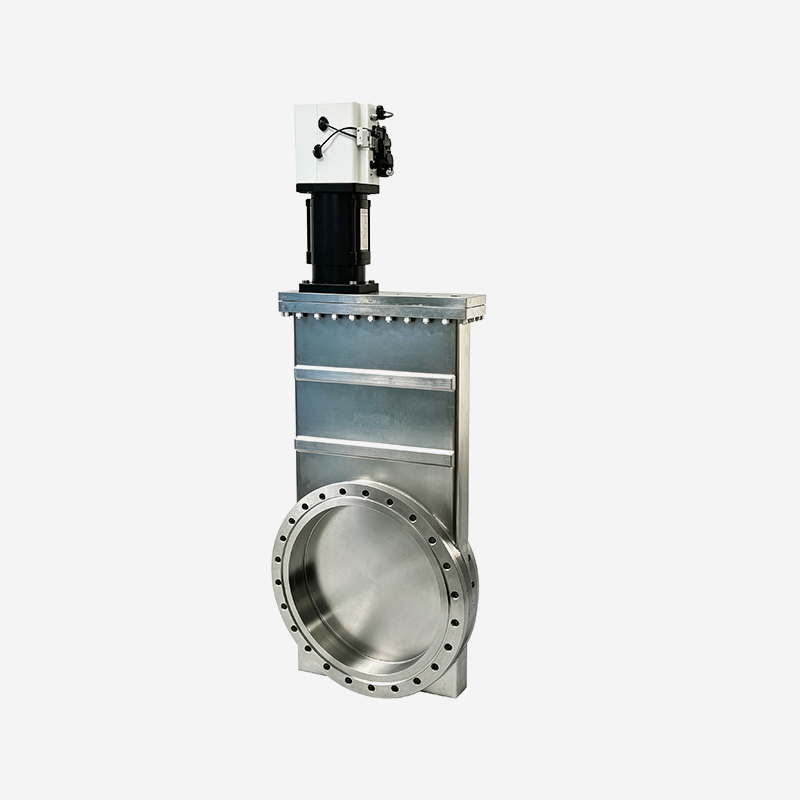 Ultra-High Vacuum Gate Valve with CF Flange and Metal SealDesigned for UHV systems requiring base pressures below 10^-9 mbar, this pneumatic valve uses a CF flange and copper gasket to ensure a reliable metal seal.View Product →
In semiconductor and photovoltaic manufacturing, wafers and glass substrates must move horizontally from a transfer chamber into a process chamber. A round gate valve limits the width of the substrate that can pass through. A rectangular gate valve solves this problem by shaping the passage as a rectangle.
Rectangular gate valves are common in transfer chambers, cluster tools, and photovoltaic inline equipment. When open, the rectangular gate retracts into an upper reservoir, exposing the full rectangular passage. The sealing area is larger than a round valve of comparable bore size, so the actuator must provide more closing force. A pneumatic actuator with a bellows-sealed stem is the usual configuration, because it keeps the process side clean and handles the reduced available space.
When a vacuum transfer chamber must handle rectangular substrates, a rectangular gate valve for vacuum transfer applications is the correct solution.
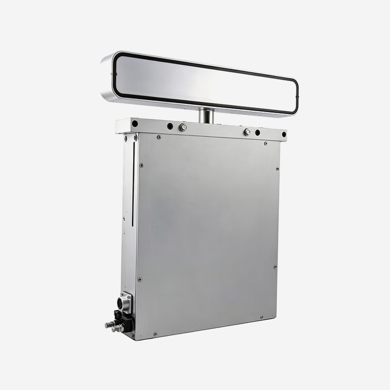 Rectangular Gate Valve for Vacuum Transfer of SubstratesThis rectangular gate valve shapes its passage as a rectangle to accommodate flat substrates like wafers, enabling smooth horizontal transfer in vacuum chambers.View Product →
A faulty gate valve usually fails outside the main seal face. The stem seal and the actuator are the components most often responsible for downtime. Understanding the weak points helps maintenance teams plan preventive action.
| Failure Mode | Root Cause | Mitigation |
|---|---|---|
| Gate seizure | Process residue or degraded lubricant on the gate | Use residue-compatible materials, schedule periodic bake-out |
| Stem seal leakage | Worn O-ring or bellows fatigue | Use bellows-sealed stems for critical process, replace proactively |
| Limit switch drift | Mechanical play from accumulated vibration | Use latching limit switches, verify position feedback during PM |
Machining precision determines how long a gate valve will hold its seal. A valve body that is machined from a single stainless-steel forging holds tolerances better than a welded assembly, because welding introduces distortion that can propagate into the flange sealing face.
Buyers should evaluate three points before placing an order:
SUNFUN Group has been active in precision manufacturing since 1986 and is able to machine parts at a 0.001-millimeter precision level, covering components from 0.1 grams to 150 tons. This capability is decisive in manufacturing gate valve bodies and flanges, because the fit between machined parts determines the uniformity of the gate stroke and the repeatability of the vacuum seal.
For a detailed look at how precision machined parts are manufactured and validated, read our guide on how precision machined parts are manufactured.
The difference is in flange standard and sealing material. High vacuum gate valves use KF or ISO flanges with FKM O-rings and maintain pressures down to 10-7 mbar. Ultrahigh vacuum gate valves use CF flanges with oxygen-free copper gaskets and maintain pressures below 10-10 mbar.
For normal production use with moderate cycling, schedule an inspection every 6 to 12 months. If the valve cycles more than 1,000 times per day, shorten the interval. Focus on the stem seal, the gate surface condition, and the limit switch alignment.
Yes, but this mode is not ideal. When a differential pressure of one atmosphere is applied across the closed gate, sealing surfaces wear faster. Some manufacturers define a separate atmospheric-pressure rating. Always check the manufacturer's rated differential pressure before using the valve in a vent-up or vent-down sequence.
The simplest way to reduce risk is to follow a structured checklist:
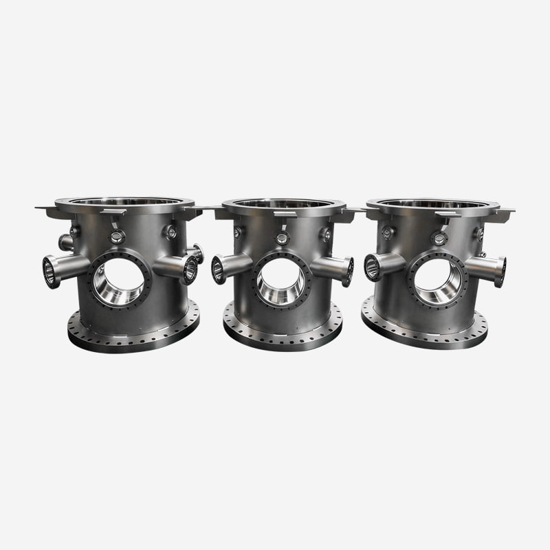
Meeting HV and UHV standards, these chambers are rigorously helium leak-tested to ensure ultra-low l...
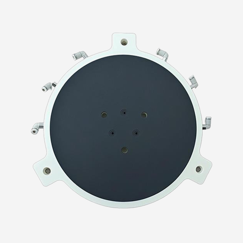
Product Features High cleanliness: Ceramic material, no metal ion contamination, smooth surface (Ra≤...
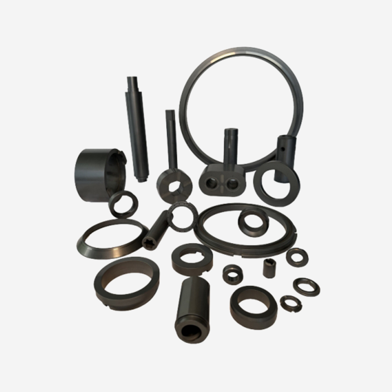
Silicon carbide materials have extremely high hardness and strength, excellent wear resistance and a...
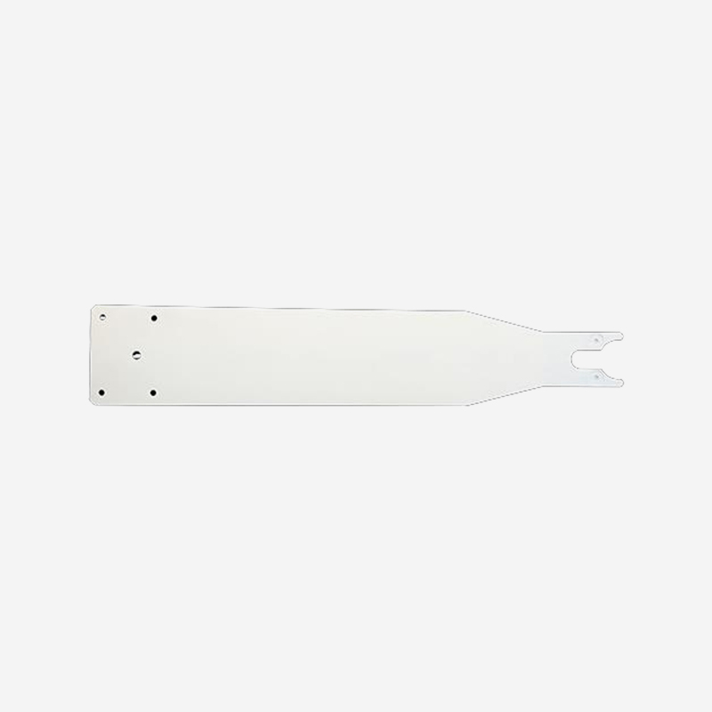
Product Features Hard and stable: High hardness,wear-resistant and durable, not prone to deformation...
Ready to Innovate Together? Contact Our Experts.

Contact Us
Address: 288 Shande Road, Shanyang Town, Jinshan District, Shanghai, China TEL/WhatsApp:Mobile terminal